Delorimier Shops of the Canadian Pacific Railway
Rolling stock and steam locomotives 1850 to 1900
General characteristics and maintenance challenges
How the Canadian Pacific Railway kept them rolling
General characteristics and maintenance challenges
How the Canadian Pacific Railway kept them rolling
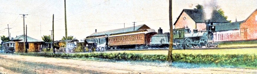
From an old postcard :
In Sherbrooke, Quebec, at the "CPR station", on some unknown date ...
you can observe the technology at this bustling transportation hub.
At the left an electric streetcar, then horses with carriages and wagons,
and a typical railway locomotive and passenger equipment from the late 1800s.
It looks as if the railway equipment is being switched.
Many railway lines meet here ...
so equipment is probably coming from, or going to, different railway lines.
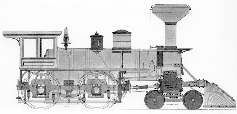
The "Standard Locomotive" 1850-1900
Below, is a nice phantom view of the standard locomotive of this era.
Water and wood enter the cylindrical boiler and the square firebox below it ... at the left side of the image.
Smoke and steam travel to the right of the image ... following separate paths along the boiler cylinder.
Metered doses of steam move a single piston on each side of the locomotive in sequence.
The pistons push and pull driving rods to turn the large driving wheels.
On the "steam exhaust phases" of piston movement,
spent steam moves vertically from each cylinder ...
into the hollow smokebox (which forms the front of the locomotive) ...
and continues vertically out the smoke stack.
Using Bernoulli's Principle, this vertical blast of spent steam sucks combustion gases from left to right ...
along the length of the locomotive boiler interior through flue pipes ...
and sucks oxygen-rich air into the firebox for efficient burning.
In other words, waste piston steam provides a draft for the fire.
This particular design of locomotive was
extremely
successful in North America - performing most of the work between 1850
and 1900. Some have suggested that this arrangement of having a light
front end, with a little swivelling pilot wheel "truck" to guide the
locomotive around
curves ... and a heavy back end with the firebox and most of the boiler
sitting over the driving wheels ... was the most perfectly balanced
steam
locomotive ever created. Or, maybe they were just being kind of wistful
for the smell of wood smoke and tallow lubricant when they were saying
that.
Most of the locomotive structural frame rests on the axles attached to the large driving wheels. The main part of the frame provides support for the cab, the firebox, and the large amount of water that jackets the firebox ... and the firebox's network of flue tubes which run within the cylindrical boiler to a point just to the left of the smokestack.
Look again at this main frame sitting over the driving axles. A necessary innovation of this era, was the system of springs and equalizers. They ensure the driving wheels follow the contours of the rough pioneer railway track ... almost like the independent suspension for each wheel on an automobile.
If the driving wheels were not kept in constant firm contact with the rails:
Innovation without standards
The earliest engine-eers were actually professional engineers or those with a similar aptitude for invention, innovation and practical metal bashing. At first there were no standard locomotive blueprints, railway equipment specifications, or government regulations for guidance. On their own, the inventors had to discover which bigger, better design might just waste fuel, hammer the track to bits, shake itself to pieces, derail too frequently, explode, or just sit there hissing. The inventors had to learn quickly.
What was it really like during the dot-steam boom ?
As the railways started in Canada in 1836, it was like a whole word run by beta software ... you know the type.
The earliest locomotives were Macs; 4.77 mHz PCs; TRS-80s; Commodore (Vanderbilt) 64s; etc.
After 100 years of government regulation to protect workers and the general public, it is hard to picture the railways of 1850.
Most of the locomotive structural frame rests on the axles attached to the large driving wheels. The main part of the frame provides support for the cab, the firebox, and the large amount of water that jackets the firebox ... and the firebox's network of flue tubes which run within the cylindrical boiler to a point just to the left of the smokestack.
Look again at this main frame sitting over the driving axles. A necessary innovation of this era, was the system of springs and equalizers. They ensure the driving wheels follow the contours of the rough pioneer railway track ... almost like the independent suspension for each wheel on an automobile.
If the driving wheels were not kept in constant firm contact with the rails:
- They might slip, causing the locomotive to momentarily lose
traction and buck against the momentum of the train ... breaking link and pin
couplers and possibly derailing the train.
- Particularly on a curve, a driving wheel turning but momentarily not in contact with the rail, might climb up and over the rail, derailing the locomotive.
Innovation without standards
The earliest engine-eers were actually professional engineers or those with a similar aptitude for invention, innovation and practical metal bashing. At first there were no standard locomotive blueprints, railway equipment specifications, or government regulations for guidance. On their own, the inventors had to discover which bigger, better design might just waste fuel, hammer the track to bits, shake itself to pieces, derail too frequently, explode, or just sit there hissing. The inventors had to learn quickly.
What was it really like during the dot-steam boom ?
As the railways started in Canada in 1836, it was like a whole word run by beta software ... you know the type.
The earliest locomotives were Macs; 4.77 mHz PCs; TRS-80s; Commodore (Vanderbilt) 64s; etc.
After 100 years of government regulation to protect workers and the general public, it is hard to picture the railways of 1850.
So here's a picture to help ...
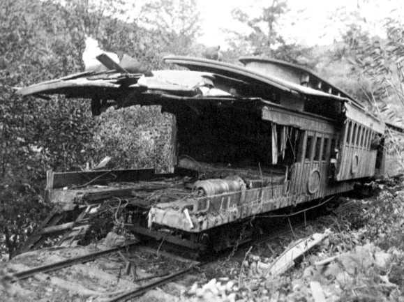
On a US railroad, these ornate, circa 1850 passenger coaches show why government regulation of railways was necessary.
Without resistance to "buff" (longitudinal) forces, a collision or headend derailment often caused wooden passenger cars to "telescope".
(In this late 1880s accident, 64 people died)
The earliest coaches were wooden shacks, on wooden beam frames, rolling along on iron & steel 4-wheeled trucks (wheelsets).
They were heated by wood or coal stoves.
Had that overturned stove been in use, there wouldn't be much wreckage for us to inspect.
Notice how light the rail is too !
Supporting a coast to coast railway
CPR in the East, 1885
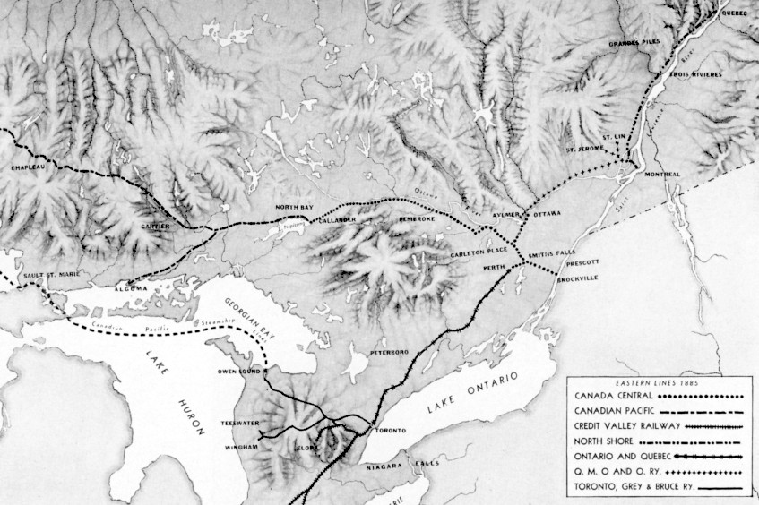
On this map, you can see the extent of
the CPR and all the lines it owned and/or leased for 999 years and/or operated in eastern Canada as the last
spike was being driven. Back then, everyone was into mergers and
acquisitions. The CPR "grew by acquisition" in the east. The story
of its "growing by the spikemaul" west of Callander, Ontario ... [pause for effect, deep voice] ... is
... Canadian ... legend.
What usually gets less attention is how this cobbled-together and scratch-built system actually functioned.
Here are a few ideas:
So, 1850-1900 there was NO convenient local "dealer service" for locomotives :
What usually gets less attention is how this cobbled-together and scratch-built system actually functioned.
Here are a few ideas:
- As you have seen, railway cars were mainly made of wood and the "barriers to entry" for the railway car construction industry were low ... you just needed wood, skilled carpenters, and a big shed for them to work in ... and a few specialized iron or steel castings or fabrications to bolt on or plunk underneath.
- As the CPR railway system was developing, our "standard locomotive" above was being built by :
- Baldwin Locomotive Works, Philadelphia
- Canadian Engine and Machinery Company, Kingston, Ontario
- Danforth Locomotive and Machine Company, Patterson, New Jersey
- The Hinkley & Williams Works, Boston
- The Portland Company, Portland, Maine
-
Rhode Island Locomotive Works, Providence ... Rhode Island
- For most of its first few decades, the CPR was always short of locomotives and bought from a number of different suppliers - sometimes waiting in line for deliveries.
- Over the years, companies in Scotland, England and Germany, sometimes built "American-style" locomotives to CPR specifications.
So, 1850-1900 there was NO convenient local "dealer service" for locomotives :
The valve gear, pistons, driving rods and other "drive train" precision parts weren't readily interchangeable between all these locomotive brands.
Fortunately, sheet metal and bars, rivets, pipes, cast wheels, axles and bearings made up much of the locomotive,
and with well-equipped shops with powerful cranes,
specialized railway employees could repair, rebuild and manufacture these elements.
Auxiliary appliances (headlights, whistles, bells, etc.) and gauges were often interchangeable and could be switched or bought by the case.
The specifics of this generalization are infinitely debatable
among the members of the Loyal Order of Rivet Counters.
But my point ...
for the other people who have no
Canadian railway history inspired tattoos
is ...
Maintaining
different locomotives
from different acquired railways
from different builders
with inherited and/or newly recruited maintenance forces
in small, geographically scattered locomotive shops
would not have been easy for the early CPR.
To survive, the CPR needed to
1. Develop an efficient system to keep its rolling stock (locomotives AND cars) rolling.
2. Standardize its rolling stock over time to make future maintenance more efficient.
The CPR needed to use standardized :
spare parts ...
efficient procedures ...
worker training and skills ...
to provide ...
increased reliability of its equipment ...
which was spread all across the Canadian wilderness.
Common railfan tattoos: Sydney 4 - 8. 5 Semper Fer
CPR organizes its maintenance
These days, some old Canadian military helicopters require 30 person-hours of work for each hour flying. I don't know what the ratio of maintenance hours : operation hours was for early steam locomotives. However, the model for daily steam locomotive maintenance was closer to the helicopters' ... than to a domestic automobile or even a modern high mileage highway truck. As a result, roundhouses were maintained every 125 miles or so to ... remove ashes ; wash out boilers ; fix minor steam leaks and other mechanical defects ; lubricate, repack or replace bearings ; refill tenders ; clean ... on and on.
But when the boiler was due for rebuilding ; the "power train" and suspension were worn down ; a frame was cracked ; system upgrades were mandated ...
Big stuff required a big "back shop" full of parts, with a big crane.
Before 1885, contractor rolling stock and CPR revenue-producing rolling stock west of Lake Superior (often originally delivered by rail via US lines) ... was isolated from CPR' s eastern shops. This was because the difficult area north of Lake Superior was the site of the "second to last, Last Spike".
In the longer term, it would not have made sense to haul a dead damaged locomotive 2000-3000 miles for major repairs in Montreal. So shops with significant capacity were being built in Winnipeg. But with the opportunity to pinch pennies in person not far from the headquarters in Montreal ... you can bet that the CPR would retain its greatest repair capacity in Montreal for about a century.
At the very beginning, CPR used the following acquired shops for its heavier work :
Canada Central Railway ... Locomotive shops at Carleton Place, Ontario ; Car shops at Perth, Ontario
Quebec Montreal Ottawa & Occidental ... a roundhouse and small shop at Hochelaga
To take you back to the general environment, here is a postcard view :
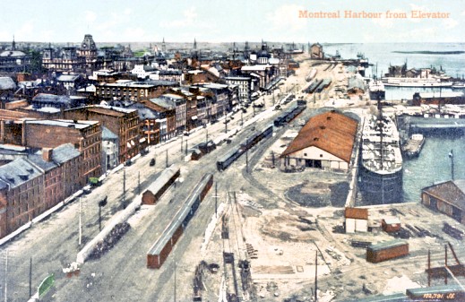
Here is the Grand Trunk (west) end of Montreal Harbour.
The Grand Trunk Railway (eastbound from Toronto - today the CNR)
ran along the southwest edge of Montreal Island ...
it then crossed the Victoria Bridge to the south shore of the St. Lawrence,
and continued to the port of Riviere du Loup - close to the mouth of the St. Lawrence.
I guess that this view is from 1900 or a little later.
There are no comedy festivals, roller bladers, or busking mimes to be seen back then at the "Old Montreal" waterfront.
At the right lower corner, you can see a boxcar which has been taken off its trucks, serving as a wooden shed.
There is an island, downstream from us, near the right horizon ...
Imaginatively named Ile Ronde is just offshore from the CPR Hochelaga Shop at the CPR (east) end of Montreal Harbour.
Delorimier Shops layout
The Carleton Place locomotive shops were nice and central on the CPR system. Parts of the old stone railway complex still exist today.
However, the CPR needed a much greater rebuild and repair capacity for its rolling stock. So it built its "New Shops" near the waterfront at Montreal, just west of its Hochelaga facility.
Other advantages of this spot :
- Many railway supply companies were located in Montreal so funny parts were handy or could be quickly obtained.
- Imported heavy machine tools, and rolling stock equipment could be brought in conveniently by ship.
- Montreal had the capacity to provide a steady supply of skilled and/or cheap labour - depending on the demands of the work.
- Proximity
to Headquarters. The CPR still had financial challenges and some
administrators liked to "help" the work along as much as possible.
The "New Shops" ... more properly The Delorimier Shops
(because they were on a street named Avenue de Lorimier - and I will
explain that) ... were connected to the CPR mainline by August 1883.
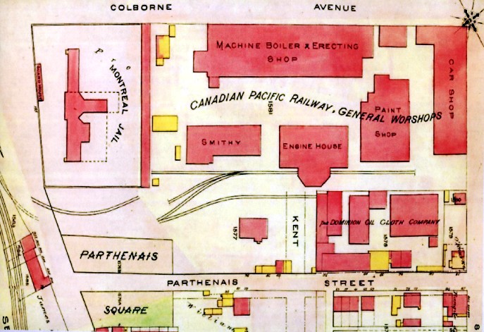
These plans are from a city atlas, and the technique for updating seems to have been a cut and paste process ... with real scissors and glue. That's why some of shop track leads don't line up. As you conclude from the plans, locomotive overhauls and building from scratch, and heavy freight car and passenger car work, could be done here. Hochelaga and other shops on the line handled most of the simpler car work.
I have concluded that the engine house had a covered turntable (under the half octagon) so snow would not have to be shovelled out of the turntable pit in winter.
The transfer table probably operated from the track stub near the paint shop ... up to the top of the white column with the letters ("SHO") as in WORSHOPS (?!)
A transfer table is a long rectangular "tray" on which track has been laid - like they use on a turntable. A car or locomotive for shopping rolls onto the tray. But while a turntable spins around, a transfer table carries the rolling stock in a direction perpendicular to its normal direction of travel. When the rolling stock is lined up for the appropriate servicing door, they roll the rolling stock in off the tray. On a relatively small parcel of land like this, transfer tables make the best possible use of space.
So at Delorimier, a single transfer table operating along that vertical white column, keeping rolling stock parallel to the yard tracks,
could deliver the rolling stock to, or between :
could deliver the rolling stock to, or between :
- the erecting shop building,
- the car shop,
- the paint shop.
A look inside Delorimier
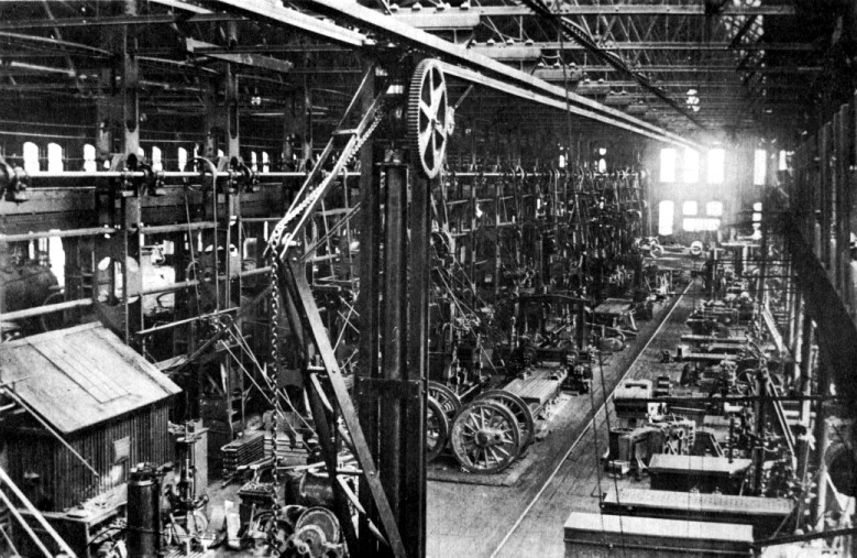
Above, you can see a photograph of the
interior of the locomotive shop. For scale, there are 5-6 foot locomotive
driving wheels in the centre. A locomotive boiler can be seen at the
left edge of the photo.
An interesting hoist is in the foreground. With a guideway above and a metal rail to roll on, I wonder if the crane uses electricity from a source above.
A fascinating aspect of this shop is that the machine tools are driven by belts coming from a central rotating shaft at the upper left. A central steam plant would keep the shaft spinning. While air or electricity driven tools would be safer than having all those belts whirring around where people were working ... I'm guessing that air and electric tools weren't readily available, affordable, or "proven" to the satisfaction of the railway bosses at this point. So until that day comes, keep your shirts tucked in, fellas.
Two Solitudes ... again
Delorimier Shops were on Avenue de Lorimier ...
but on the plan, it is Colborne Avenue?
John Colborne, First Baron Seaton (1778-1863) ... was a widely experienced British career soldier (Waterloo, etc.) ... who applied his knowledge to the administration of British colonies when peace came. On his retirement in his 80s, he was promoted to the highest rank in the military, that of Field Marshal.
Francois-Marie-Thomas Lorimier, (called 'Chevalier de' Lorimier - but born in Canada after the French Revolution) born 1803, Saint-Cuthbert, Lower Canada. A notary who participated in the Patriote Rebellions for responsible government and local control of tax monies ... among other issues. Previously, the Patriote Party had held a majority in the elected Lower Canada Assembly ... which had little legislative power.
Colborne was an able military leader who personally took command of the troops at the Battle of Saint-Eustache during the first rebellion in late 1837. Nearly 100 Patriotes were killed ... first as they fired from the town's church and other stone buildings ... and later as they fled these buildings which the troops had set on fire. Lorimier, acting as a Patriote militia officer, had fled Colborne's guns and bayonets when things seemed hopeless. An idealist with Liberty Fever, Lorimier abandoned his family and practice in Montreal, regrouped with other Patriotes in Vermont, and participated in uprisings again the next winter.
After his imprisonment and trial by British court-martial in 1839 for being a Patriote leader, Lorimier's wife appealed to Colborne to spare her husband's life. Colborne did not respond to her letter. Lorimier was among 12 Patriotes hanged for their part in the rebellions.
Colborne was a reasonable administrator and better than most of the duds Whitehall sent over (including Lord Durham, with his two warring bosoms, or whatever) at understanding the practical challenges of ruling British North America. However, he was first and foremost a guardian of the successful British system of government ... and thinking too far beyond orthodox Victorian thought was not a policy option when it came to people convicted of high treason.
A carpenter from Saint-Timothee (where Lorimier was active during the 1838 rebellion - "Patriotes, Part Doo" - around Beauharnois), one David Gagnon, was among 58 Patriotes shipped off to Tasmania for six years before successful appeals had them all pardoned by Queen Victoria. A public subscription was organized to pay for their passage back - as the return trip was 'not included' in the original 5 month long Tasmanian 'Devil May Care' Penal Colony Cruise. The original intention had been to keep them there for life.
Before the pardons - as the losses and punishments from the Rebellion became entwined in the Canadien identity - the evocative lyrics of Un Canadien errant were written and applied to a traditional folk song. Un Canadien errant became a Canadien anthem for the the absent Patriotes who were exiled far away from their native land. Over time, it was sung as a "chanson a repondre" all over North America as Canadiens travelled to remote areas to find work.
Of the mainly American-born rebels who simultaneously rose up in Upper Canada over most of the same issues ... none was executed and a slightly larger quantity was bundled off to Australia. The British authorities were savvy enough not to start hanging ex-American-Upper Canadians ... with the massive population of the new republic so close and so sympathetic to fighting for democracy.
The British administrators of the Upper & Lower Colonies probably figured that no one would notice that the Lower Canadians received harsher treatment 170 years later, eh?
Of course they were right ... only the Quebec school system ; museums - general or with a Patriote specialty ; and a recent controversial film about Lorimier's last 24 hours ... preserve this information.
In "rep-by-pop" post-Confederation Canada - in 1883, 44 years after his execution - Lorimier's widow and two daughters were found to be living in poverty. A collection of $1000 was taken up by private citizens and given to her as compensation. Montreal city council renamed the street from Colborne to Delorimier in 1883 as well.
Lorimier's incarceration and hanging had taken place at the jail shown adjacent to the CPR shops in the plan above.
So in this website's typical fashion, I have taken you to Tasmania and back - to explain a Montreal street name.
Rolling stock: wood and labour
From 1900, here an illustration showing the official specifications for the ladders, roofwalks, grabirons and hand brake rigging for a standard wooden boxcar. As you know, before train air brakes were operated by the engineer, the brakemen would run from car to car, along the roofwalks, stopping at each hand brake wheel to wind on the brakes. Into the 1950s, roofwalks were maintained on freight cars.
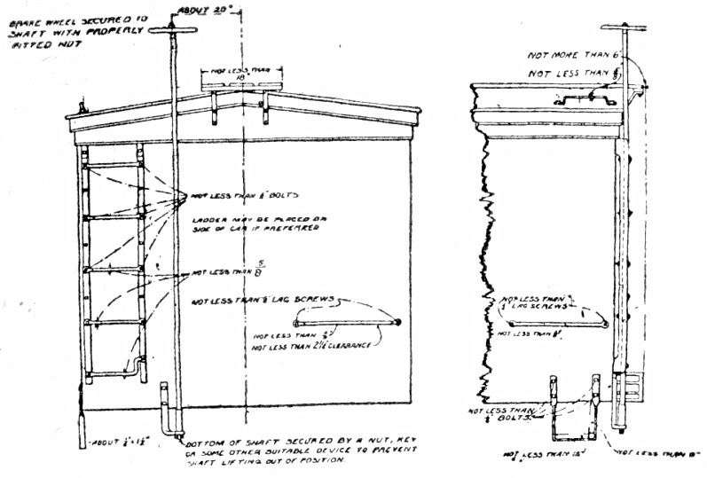
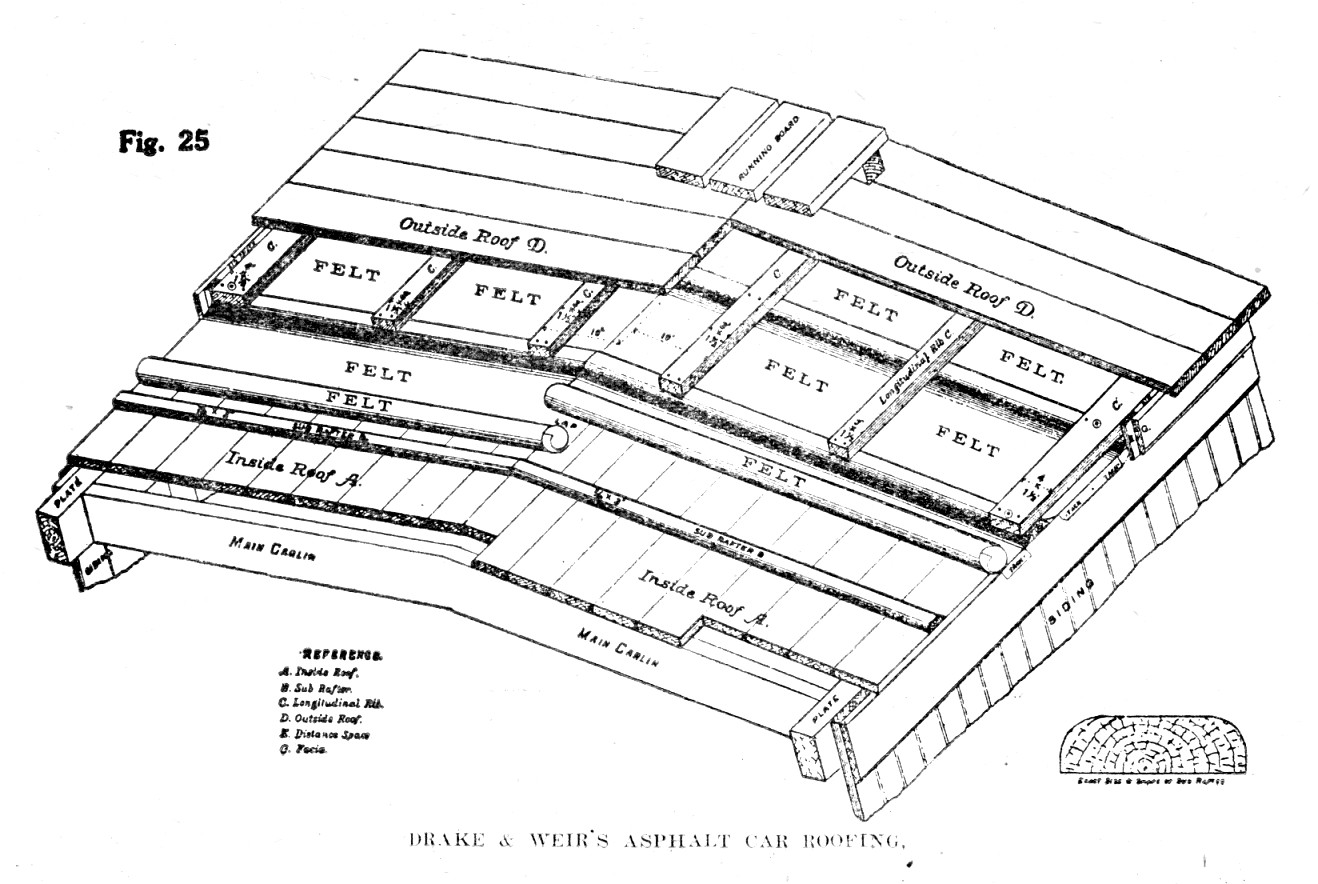
The illustration below, shows how you
take a wooden shack on wheels (an early boxcar) and protect its
contents from rain and snow. This was back in the days when labour and
wood were cheap. In addition to the special asphalt roofing, and
multiple layers, the roof would be kept well-painted. The diagram even
specifies the orientation of the wood grain to help shed the water.
To keep all its boxcars maintained, the CPR needed car shops.
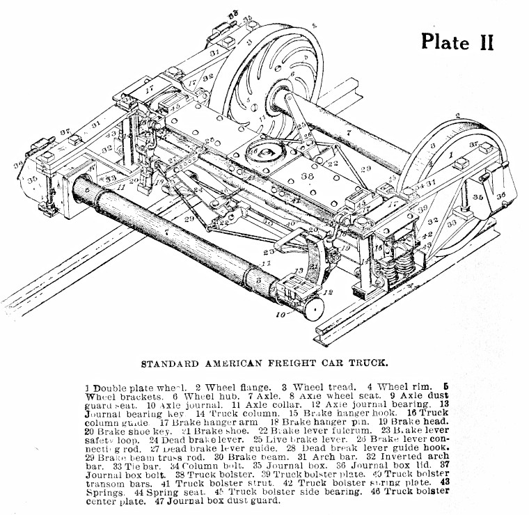
Below is an old "arch bar" truck. This
name distinguished it from newer "cast trucks" which feature
solid castings ... rather than the assembly of curved metal bars bolted
together which you see here ... forming the truck's side frame.
Cutting, bending, and bolting standard metal bars together was "state of the art" when the CPR began its operations. Purchasing, constructing, storing, assembling, replacing, repairing, adjusting and scrapping all these parts as they wore out, demanded a good system of procurement and stores, skilled workers, supervision, and a system to co-ordinate regular repair and renewal of freight cars.
Please memorize the names of the 47 labelled items for the exam.
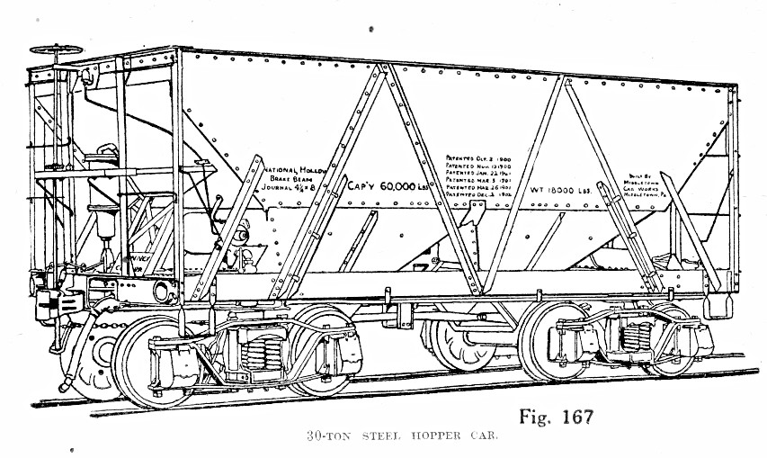
While wood was fine to begin with, steel
construction became necessary as loads became heavier and locomotive
pulling power increased. Steel could also be bent into funny shapes if
you required it. Coal cars such as this (also known as "hopper" cars because of
the "funnels" in the bottom through which the contents emptied by gravity) were
required in great numbers because coal was the fuel which powered
industry ... and the railways. At the mine tipple, coal would come
crashing down into the car body and steel was certainly more durable that wooden boards to
take that kind of punishment.
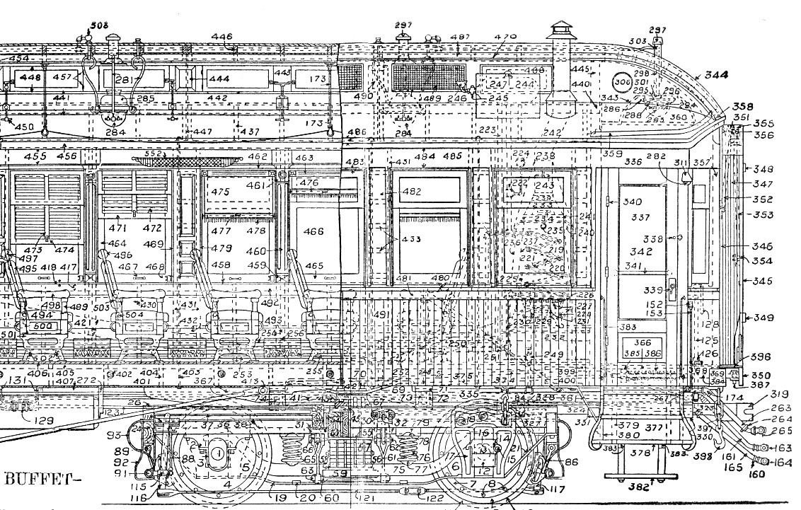
As our rolling stock illustrations
become more complex and impressive, take a look at the complexity of
the cars in which humans were riding by 1900. This was an
illustration showing features of different types of
passenger cars, so there is extra variety in its parts. However, it is
still more complex than the previous box and hopper cars.
Up in the clerestory, you can see gas lighting appliances and the valves to control the flow of gas. A stove; a car-length signal cord; three connecting hoses for airbrakes, the communicating signal, steam heat (the latter if you don't chose the stove for your car) are visible if you stare at this long enough ... and just about everything else is made out of wood. Let's go with the safer steam heat !
Up in the clerestory, you can see gas lighting appliances and the valves to control the flow of gas. A stove; a car-length signal cord; three connecting hoses for airbrakes, the communicating signal, steam heat (the latter if you don't chose the stove for your car) are visible if you stare at this long enough ... and just about everything else is made out of wood. Let's go with the safer steam heat !
The Iron Horse
The Boiler - Pressure vessel
But the most challenging item to design, build and maintain at the CPR's Delorimier Shops in Montreal was a steam locomotive.
- The left third is the firebox, with a diagonal brick arch to cause the coal gases (including heat-rich methane) to swirl and around and burn completely and efficiently.
- The middle third has most of the water surrounding the flue tubes (pipes) which took the hot waste gases to the right for expulsion.
- At the right third, the smoke box, the hot gases exit the flue tubes ... and linger for a split second ... before waste steam from the cylinders blasts them out the stack.
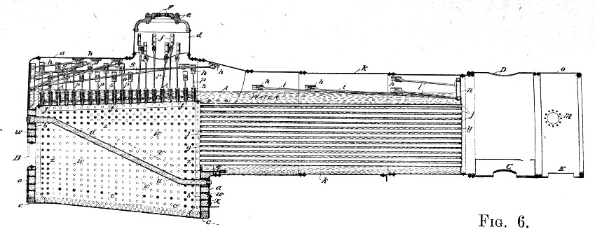
The dome at the top is the
"steam dome" where a "dry pipe" (not shown) - above water level - would take
the high pressure steam down to the cylinders to do work. The steam dome is
directly above the hottest part of the firebox with the thinnest
covering of water.
The Smokebox - Playing the Pan Pipes of Hell
The Smokebox - Playing the Pan Pipes of Hell
We are looking into a locomotive with its "front" taken off. The compartment revealed is called the smokebox. Here at the smokebox,
ALL the boiler's high pressure steam (at 10-12 atmospheres pressure) is
safely away from us inside the boiler or steam pipes. (However, you
would never fire up a locomotive in this state)
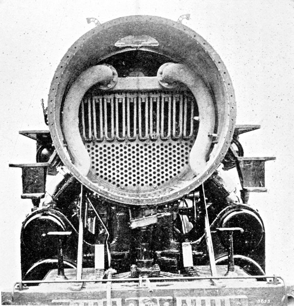
- The two big grey curved pipes carry high pressure steam
downward. The engineer has put this this steam in motion by opening the
throttle valve to a specific position (like using a lever faucet in the kitchen today).
- The steam then flows out through those big black pipes at 45 degree angles into the "little black circles" ... the steam valves.
- The steam valves use various mechanical "tricks" (you'll see !) ... to meter the desired amount of steam into the partially hidden "big black circles" ... the cylinders ... which contain the pistons.
- The high pressure steam moves the pistons to propel the locomotive ... again the valves do all the magic.
- The waste steam from each piston is released, via the valves again, to the centre of that big black "saddle" casting below the grey smokebox area.
While all this is happening, sulphurous
coal smoke is coming at us from a honeycomb of flue pipes - many of which can be seen in the bottom
third of the smokebox.
Then taking roughly one second, and in strict sequence :
When a steam locomotive is travelling at high speed, these alternating exhaust blasts are faster than a fast jackhammer breaking up concrete.
Missing from this illustration are things like a "petticoat pipe" which help to direct the waste steam's flow through the smoke box and out the stack.
Then taking roughly one second, and in strict sequence :
- The valve on one side releases pressurized waste steam from its corresponding cylinder below.
- The steam goes to an area of lower pressure (the saddle casting below the smokebox).
- The next area of lower pressure is the smokebox so the steam rushes there.
- The area of lowest pressure is "the atmosphere". This is reached through the circular hole in the top of the smokebox - the smoke stack.
- On its way through the smoke box, the blast of steam sucks the
coal smoke from the flue pipes - as if the steam is playing the
Pan Pipes of Hell (sort of).
When a steam locomotive is travelling at high speed, these alternating exhaust blasts are faster than a fast jackhammer breaking up concrete.
Missing from this illustration are things like a "petticoat pipe" which help to direct the waste steam's flow through the smoke box and out the stack.
21st Century Financial Journalism, Creative Writing Assignment : Ode to Steam Locomotion
This "one second journey" of the steam
(from valve to stack) is what gives the steam locomotive its dramatic,
lifelike sound - unmatched by other types of motive power.
The sound is so captivating and unique that business reporters (almost HALF A CENTURY after the demise of steam) still remark that
"Canadian Pacific Railway has 'chugged' its way to another year of profit".
The sound is so captivating and unique that business reporters (almost HALF A CENTURY after the demise of steam) still remark that
"Canadian Pacific Railway has 'chugged' its way to another year of profit".
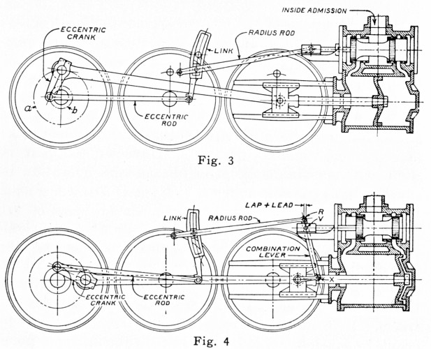
Valve Gear - Managing expanding steam efficiently
If you like puzzles, you'll LOVE figuring out the pocket watch logic of these diagrams. Please explain them to me when you get them figured out.
Three relatively simple things are happening in the diagrams below.
Below the valve "spool", is the cylinder containing the piston. The piston is more like a stick with a circle on its end. Again, lots of special shaping, chambers, and channels are involved.
While you would intuitively assume the steam only does work when it pushes the piston to the LEFT ... you can also see by studying this puzzle that the piston also does work as it travels to the RIGHT. Being an external combustion engine (no fuel is burning IN the cylinder) steam engines needed all the efficiency they could get ! Thank you steam locomotive design engineers ... after whom with affection the eccentric crank is probably named.
If you like puzzles, you'll LOVE figuring out the pocket watch logic of these diagrams. Please explain them to me when you get them figured out.
Three relatively simple things are happening in the diagrams below.
- Steam is being reduced in pressure from about 10 atmospheres to about 1+ atmosphere ... the lost steam power is being turned into useful work.
- Pistons are moving in and out, but the connected driving wheels are going round and round.
- Clever mechanical design engineers ... and conscientious locomotive engineers (i.e. drivers) ... are getting the most power possible out of the steam's energy.
Below the valve "spool", is the cylinder containing the piston. The piston is more like a stick with a circle on its end. Again, lots of special shaping, chambers, and channels are involved.
While you would intuitively assume the steam only does work when it pushes the piston to the LEFT ... you can also see by studying this puzzle that the piston also does work as it travels to the RIGHT. Being an external combustion engine (no fuel is burning IN the cylinder) steam engines needed all the efficiency they could get ! Thank you steam locomotive design engineers ... after whom with affection the eccentric crank is probably named.
The next part is sort of "chicken or
the egg". Keep in mind there is a similar set of equipment on the other
side of the locomotive. The driving wheels are permanently pressed onto
the axles which connect them ... so the locomotive's LEFT wheels'
rotation is
permanently locked to RIGHT wheels' rotation ... but the LEFT and RIGHT
side rods and valve gear are NEVER
in an identical position at any time. Everything has been carefully
designed so that somewhere, somehow, all the mechanical parts will instantly provide full power when the throttle valve is opened.
The locomotive (driving) engineer doesn't care where the left side/right side wheels, rods, valves, and pistons are positioned when he opens the throttle. All he knows is that steam will flow through through his open throttle, pass through "the valves" and push "the pistons" ... one way or the other on both sides ... then the train moves ... and he starts getting paid.
However, the locomotive engineer cares very much about the position of his "reverser" lever before he cracks the throttle.
Using the reverser, the engineer determines:
"Name three types of valve gear !"
... Rolly would always smile and demand this when we visited. I would remember Stephenson (for historical reasons) Walschaerts (from Trains Magazine) and always forget Baker. This gave Rolly the opportunity to remind me and we both relived the days of steam. My shocking lack of essential knowledge confirmed, he would then continue to another favourite question about the weight of rail used on the original CPR ...
The valve gear shown above in Fig. 4 is Walschaerts ... including an essential little addition which Fig 3 is missing. In reality, the main driving wheel (at the left) would share its power with the other two wheels through a passive connecting rod for better traction. It gets sooo complicated!
Walschaerts Valve Gear was invented by ... Egide Walschaerts, a Belgian, in 1844. There were many, many different types of valve gear invented over the years and some were more popular than others. Stephenson, named for the most memorable pioneer of the first steam locomotives on the first steam Rail Ways, was the valve gear used on early simple locomotives like the "standard" locomotive model at the beginning of this page.
Once railways got into bigger power in North America after 1900, sixty year old Walschaerts valve gear (and the similar Baker valve gear) got the nod.
Similarly, might we be using circa 1990 9-pin dot matrix inked-ribbon printers with our computers in 2050 ??
These are the types of things which design engineers thought about ... Walschaerts was ...
Old Stephenson, New Stephenson
Development during the first 50 years
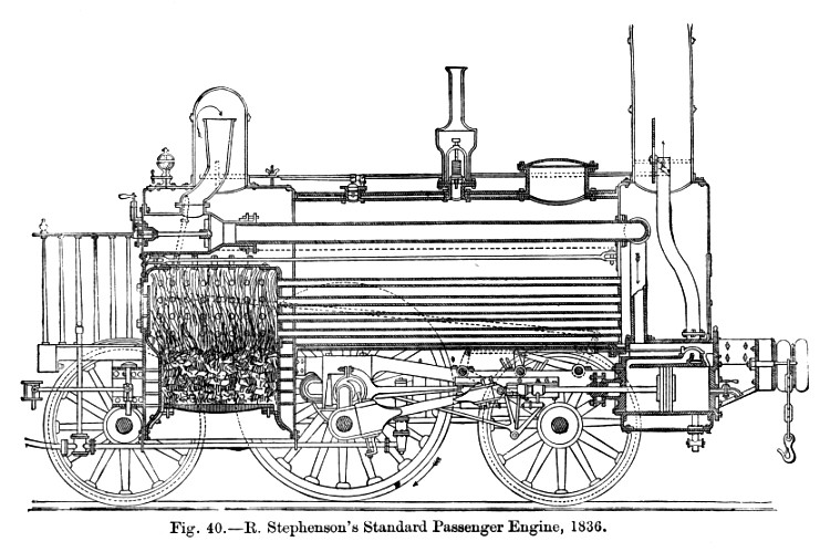
In the same year that railways began in Canada and the Patriotes were becoming restive ... here is one of Stephenson's locomotives. More or less sectioned on the median plane (or "cut in half by a buzz saw") this view shows the inner workings of a typical Stephenson locomotive. Considering maintenance and "big power" ... the cylinder and valve gear are between the wheels and under the boiler where you don't have many options. However, between 1836, 1883 (CPR Delorimier Shops) and 1900 (Walschaerts valve gear becomes popular) the basic Stephenson valve gear got bigger and better.
By now, you'll able to spot the following parts on the Stephenson engine :
In contrast to engine 285 above ...
Below is one of the last steam locomotives built at Delorimier Shops, November 1902.
It was rebuilt at the CPR Angus Shops in 1920 and scrapped in early 1939 (lifespan: 37 years).
If you care : the reverser changes the relative positions of "radius rod" and the "link".
Using the reverser, the engineer determines:
- Which way the wheels will
turn : he doesn't want to actuate the bell to announce imminent motion
... signal FORWARD motion with two whistle toots ... and then BACK his
locomotive into his train!
- That enough steam is being sent to the cylinders to start and accelerate a heavy train ... but that steam is not being wasted
when less work is required. The latter point matters to him as railways
such as the CPR regularly post a list of engineers' use of resources ...
particularly fuel !
The reverser affects ... valves and
valve gear on both sides of the locomotive ... controlling both
direction, and steam "cutoff" (quantity and timing) for each piston
movement.
The reverser's control of "cutoff" is effectively like selecting a manual overdrive on an automobile ... same speed, less fuel (steam = fuel).
The reverser's control of "cutoff" is effectively like selecting a manual overdrive on an automobile ... same speed, less fuel (steam = fuel).
"Name three types of valve gear !"
... Rolly would always smile and demand this when we visited. I would remember Stephenson (for historical reasons) Walschaerts (from Trains Magazine) and always forget Baker. This gave Rolly the opportunity to remind me and we both relived the days of steam. My shocking lack of essential knowledge confirmed, he would then continue to another favourite question about the weight of rail used on the original CPR ...
The valve gear shown above in Fig. 4 is Walschaerts ... including an essential little addition which Fig 3 is missing. In reality, the main driving wheel (at the left) would share its power with the other two wheels through a passive connecting rod for better traction. It gets sooo complicated!
Walschaerts Valve Gear was invented by ... Egide Walschaerts, a Belgian, in 1844. There were many, many different types of valve gear invented over the years and some were more popular than others. Stephenson, named for the most memorable pioneer of the first steam locomotives on the first steam Rail Ways, was the valve gear used on early simple locomotives like the "standard" locomotive model at the beginning of this page.
Once railways got into bigger power in North America after 1900, sixty year old Walschaerts valve gear (and the similar Baker valve gear) got the nod.
Similarly, might we be using circa 1990 9-pin dot matrix inked-ribbon printers with our computers in 2050 ??
These are the types of things which design engineers thought about ... Walschaerts was ...
- Relatively lightweight.
- All the gear is outside of the frames and wheels ... for easy lubrication, inspection and repair of all the moving parts.
- With the axle and frame (the inside area) clear of gear, more internal bracing could be added for greater locomotive structural strength.
- The parts which wore out were mainly "pins" which connected the rods to the wheels. Not a big deal.
- Being light, the gear inflicted less uneven wear on the valves.
Old Stephenson, New Stephenson
Development during the first 50 years
In the same year that railways began in Canada and the Patriotes were becoming restive ... here is one of Stephenson's locomotives. More or less sectioned on the median plane (or "cut in half by a buzz saw") this view shows the inner workings of a typical Stephenson locomotive. Considering maintenance and "big power" ... the cylinder and valve gear are between the wheels and under the boiler where you don't have many options. However, between 1836, 1883 (CPR Delorimier Shops) and 1900 (Walschaerts valve gear becomes popular) the basic Stephenson valve gear got bigger and better.
By now, you'll able to spot the following parts on the Stephenson engine :
- Firebox
- Steam dome and dry pipe (to get the steam from the top of the boiler)
- Throttle and main steam pipe
- Flue tubes
- Cylinder and piston
- Smokebox and stack
- Bonus question : spot the safety valve
- To become a lucky qualifier for a draw for 100 bonus points ... explain the valve gear
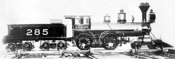
Below is the first locomotive constructed at Delorimier Shops, built November 1883.
It has Stephenson valve gear and nice clean lines. It is sitting on the Delorimier Shops transfer table.
It was rebuilt by CPR Angus shops in 1908 and scrapped in 1920 (lifespan: 37 years).
It has Stephenson valve gear and nice clean lines. It is sitting on the Delorimier Shops transfer table.
It was rebuilt by CPR Angus shops in 1908 and scrapped in 1920 (lifespan: 37 years).
Delorimier Fades Away
After 21 years of operation 1883-1904, Delorimier was replaced by the Canadian Pacific Railway's Angus Shops.
In 1900, it was becoming clear that Delorimier couldn't keep up with demand.
Since the railway's east-west completion in 1885, vast areas of the Prairies had been settled,
increasing the demand for passenger and particularly agricultural freight transportation.
The growth in Canadian commerce, population, and increasing competition from other railways
demanded bigger and better rolling stock ... and the railway's capacity grew.
Railway equipment is heavy, often complex, and has a long lifespan.
Reliable in-house construction, maintenance, repair, and rebuilding to include efficient new technologies,
enabled the CPR to maximize its use of this expensive asset.
Reliable in-house construction, maintenance, repair, and rebuilding to include efficient new technologies,
enabled the CPR to maximize its use of this expensive asset.
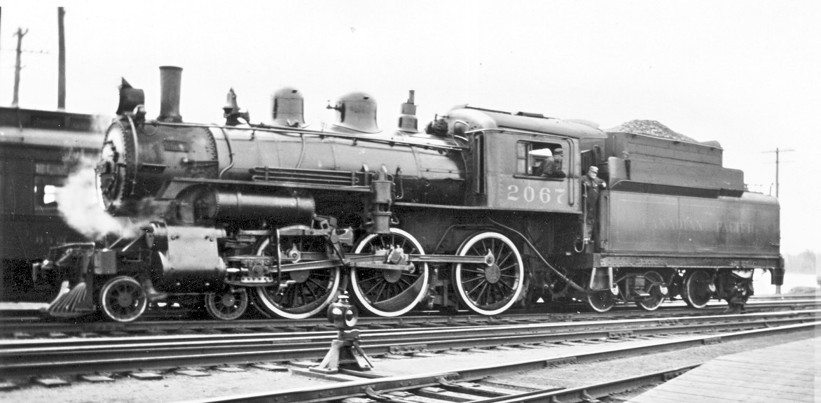
In contrast to engine 285 above ...
Below is one of the last steam locomotives built at Delorimier Shops, November 1902.
It was rebuilt at the CPR Angus Shops in 1920 and scrapped in early 1939 (lifespan: 37 years).
Fun features: The valve gear is outside and the veteran hogger has crossed the cab to pose in the gangway.
The location on the back of the photo is McAdam, New Brunswick, May 24 1934.
The location on the back of the photo is McAdam, New Brunswick, May 24 1934.
Back to sitemap