Local telegraph instruments & the local circuit ...
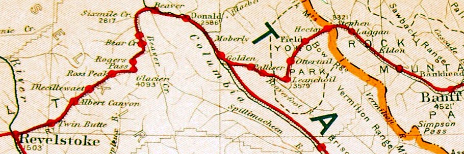
From a Canadian government atlas, here is a map with circa 1910 data.
East to west across the map ... is the Calgary to Kamloops mainline of the CPR.
Lake Louise is 'Laggan'.
The 'Big Hill' east of Field has not been replaced by the Spiral Tunnels.
The Connaught Tunnel has not yet been built to avoid Rogers Pass.
Craigellachie, just west of Revelstoke, has a telegraph station.
Red represents telegraph lines.
Red dots represent telegraph stations.
... They kept track of these things back then.
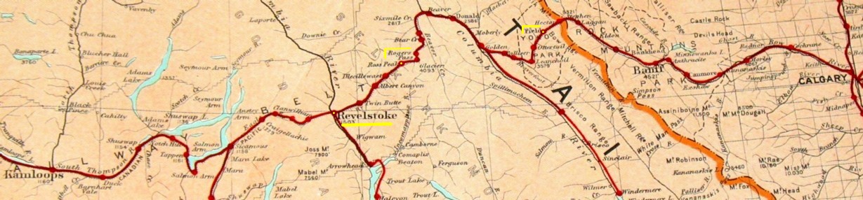
Mileages based on a 1892 timetable reprint :
Calgary - Field 133 miles
Field - Revelstoke 130 miles - hi-lited yellow
Revelstoke - Kamloops 128 miles
This is just intended as an
illustration of typical telegraph installations of the time. There is
no way for me to know exactly what equipment was used circa 1900 ...
but this area and map are interesting ... so it is being used as a
'model
location' for this little essay.
The telegraph 'main line' circuit runs Field to Revelstoke. The communications for the smooth operation of the railway and its other businesses depends on this through line working well. Some wires are probably dedicated to 'through traffic' ... others are for local train control and other messages. Large 'batteries' of cells are set up at Field and Revelstoke because they are large railway towns with extra resources and administrative staff to supervise operations. The cells may be gravity cells or perhaps lead-acid batteries are now in use.
The gravity cells are 'primary' cells which react chemically to create their own electricity. The lead-acid cells are 'secondary' cells which must be recharged from a source of electricity ... such as a stationary steam engine-driven dynamo. The larger centres would get dynamos first, while intermediate stations would get along with kerosene for light, and gravity cells to operate the local telegraph circuit.
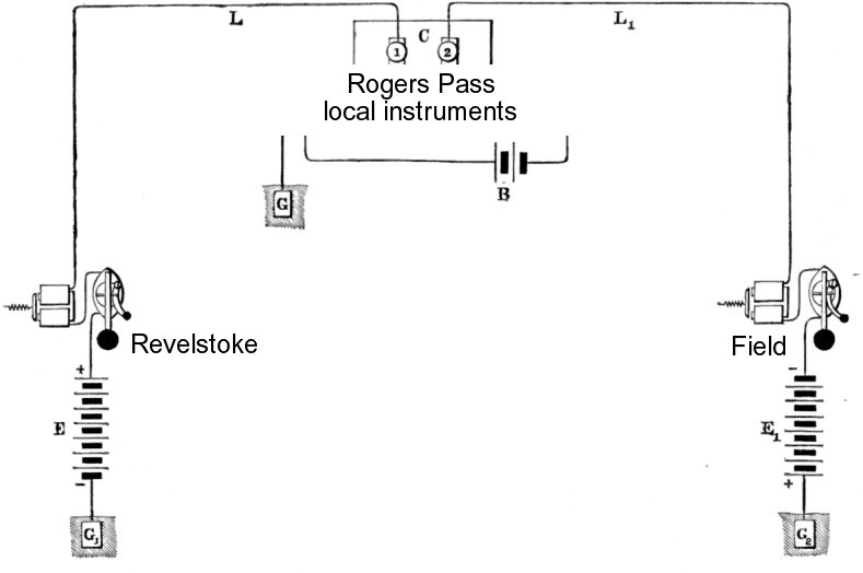
Above is a 'model illustration' of a typical telegraph circuit of 100 miles or more.
When the Rogers Pass local telegraph instruments were not in use ...
contacts 1 and 2 would be electrically bridged to provide continuity, Revelstoke to Field.
This bridging would occur when no operator was on duty ...
or if the Rogers Pass location was experiencing lightning ...
to protect the local instruments from damage.
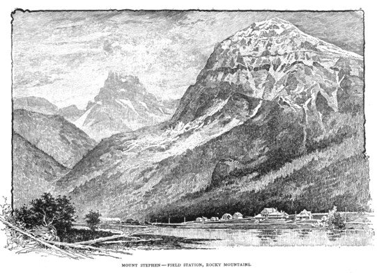
Field, British Columbia at the bottom of the CPR's Big Hill.
Travelling right to left and up through the valley will eventually take you east to Calgary.
Simplified local station circuit and instruments ...
These are the local instruments at the 'Rogers Pass' station ... another 'model illustration'.
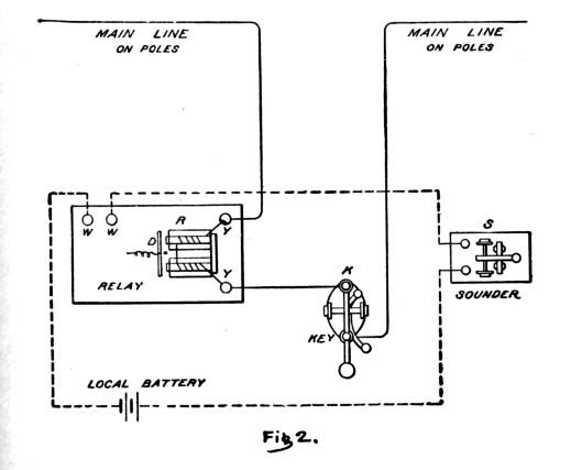
In this simplified conceptual sketch you can see that the main line wires (solid lines) work through the relay and key.
There is also a local circuit (dashed lines) working through the local battery, relay and sounder.
Not included here is the essential switchboard and the 'ground' wire ... which we will get to on the next page.
This will explain almost everything ...
This is the one 'magical' bit of
information which explains just about everything you need to know about
the local telegraph instruments.
Everything is based on a special 'horseshoe' magnet.
Everything is based on a special 'horseshoe' magnet.
In contrast to the simple, permanent horseshoe magnets which Wile E. Coyote uses against the Roadrunner ... this is an electromagnet which can be turned on by running electrical current through its coils. It can be turned off by stopping the current.
Today, many people regularly operate the highly-evolved descendants of these ancient and venerable electromagnets ... when they actuate the electric locks on their car doors ... or engage the solenoid in their car's starter.
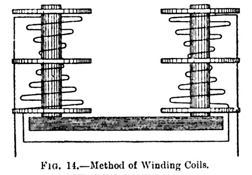
This is only a sketch of the 'wiring scheme'. It shows how the continuous strand of fine insulated wire must be routed. It also shows the 'winding scheme' for the two coils ... to ensure that the two coils don't work against each other. When completely wound, the two coils above would actually look like two spools of thread. The framework of the U-shaped magnet is made from 'soft iron'.
Some characteristics of a
good working telegraph magnet are :
1. Quickness in building the magnetic field.
2. Strength in attracting the 'armature' crisply and firmly to the end of its travel ('click').
3. Electrical efficiency : that is, the gauge of wire used ... and the number of windings ... is ideal.
4. Quickness in dropping its magnetic attraction, so the armature can be crisply returned to its de-energized position by its mechanical spring ('clack').
1892 - Telegraphs are quite essential.
Local instruments and their essential parts
Machined or 'gnarled' screws
They're everywhere !
To save time in identifying very similar parts ...
these instruments are robust, finely crafted, elegant little machines.
Most of their 'output' comes from a delicate 'give and take' ...
between electro-magnetic and potential energy (metal spring) forces.
To get them working perfectly ...
with varying ambient humidity and temperature, and varying mainline current strength ...
there are many little adjustments which a skilled operator would make from day to day.
Every machined screw you see is a potential 'finger tight' adjustment.
Generally, the top screw is the adjustment ...
the other screw (actually a round 'bolt' turning on the adjustment screw's thread)
tightens the 'adjustment screw thread' against the metal part ...
locking the adjustment.
Example of temperature extremes : unheated closed station on a prairie winter night ... roaring fire in the station office stove the next day.
Example of current strength varying : Hours of drenching rain causing current to bleed off from miles of telegraph line.
Telegraph Key
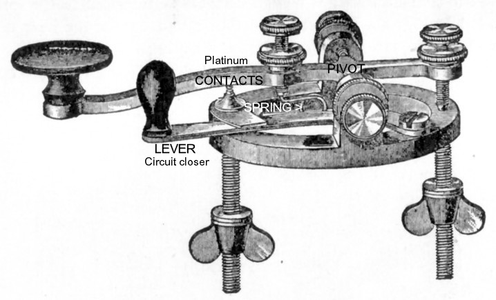
The telegraph key is used by the operator (also known as a 'brass pounder' ... never a platinum pounder) to produce messages in Morse code.
This key uses wingnuts to secure it to the station desk.
The fingers of the operator depress and release the round key to energize and de-energize the circuit.
|
A Strange concept for us today ...
which is essential to understand ...
As mentioned earlier in
these articles, this is a CLOSED CIRCUIT SYSTEM.
The 'model' circuit from
Revelstoke to Field above is always ON ... energized.
As you can imagine ... if YOU were buying today's 'dry cell batteries' to power the circuit, it would get very expensive because they would lose power quickly. HOWEVER, using the 'wet' Grove or Gravity primary cells this was not a problem. In fact, it was generally better for the Gravity cells to react continuously so the various ions wouldn't combine in 'bad' ways and gum up the electrodes. So power is always travelling through the wires and always travelling through every key, relay and connected sounder on 100+ miles of telegraph line. The magnets are always ON and pulling on the armatures. 'But I always understood
that pressing the springy key DOWN completes the circuit and sends the
signal !!'
... well that is correct. The secret is the 'circuit closer lever' (shown on the key above). Before sending, an
operator must 'BREAK' ... the circuit. The circuit closer
lever is moved counter-clockwise out of that little clip.
Then ... all along the line ... all the operators hear the 100+ mile circuit de-energize. This is because their sounder and relay magnets all let go ... and the armatures click back into a de-energized position ... from the force of their 'return' springs. Then, the breaking
operator depresses and releases the key
to alternately energize and de-energize
all the magnets from Revelstoke to Field as the Morse message is sent
and everyone hears it.
When the message is completed, the circuit closer lever is returned to its original position by the sending operator ... again making the circuit continuous from Revelstoke to Field and all magnets along the line are remain energized. |
Telegraph Sounder
This is the noise-maker which the receiving operator uses to 'hear' what the distant sender is 'saying'.
Sources suggest that listening to Morse 'language' becomes quite natural - like any other second language.
Below, you can see the coils which draw the 'armature' down as the distant message sender depresses their telegraph key (energized click).
Whether the sound is to be a short or long (dot or dash) is determined by ...
the time between the 'energized click' and the 'spring return click'.
Railways didn't use 'SOS' as a distress signal,
so here is a slow motion example of (O _ _ _ ) and (S ... ).
with EC = energized click ; SRC = spring return click ; unit = unit of time ...
'O' sound:
EC unit unit SRC
EC unit unit SRC
EC unit unit SRC
'S' sound:
EC unit SRC
EC unit SRC
EC unit SRC
Slow motion: These two letters would actually take 1-2 seconds to send.
(Purist detail : The 'timing' of features of each letter may differ depending on which 'Morse Code' one is using.)
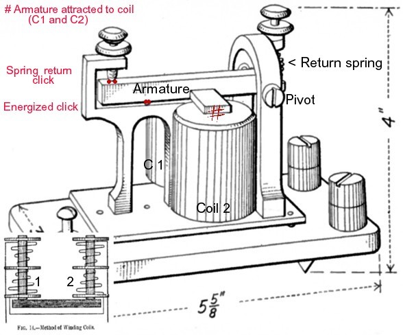
My insert at the lower left corner just shows that the open end of the U-magnet is facing 'up' on the sounder.
The 'spool of thread' coils, with their very fine wire, are protected with a covering.
The energized magnet acts at the # ... and also behind the armature on the other side too.
When the coils de-energize, the return spring pushes down and seesaws the armature back up ...
until it clicks against the set screw at 'spring return click'.
Heck ... you can simulate these click sounds if you just depress and release your mouse button slowly or quickly !
The clicking and spring return work just like a telegraph key.
The Relay
After travelling through the
cold, snowy, rainy mountains all the way from, let's say, Field to
Rogers Pass ... the electrical signal pulses sent by the battery at
Field are getting pretty weak and tired. They can't be counted on to
click a sounder's heavy armature strongly and consistently enough to
enable
the signal to be heard by the operator at Rogers Pass - stations can be
noisy places. So the sounder
is not directly wired to the main line ... there is no point.
Originally, the relay
was developed to boost the 'binary code' pulses of the distant
telegraph message with extra electrical strength ... and send them on
their merry way.
As if the message was a torch in
a relay race with a fresh
runner ...
I was fortunate to find the
simplified diagram below which explains exactly how the relay is
designed ...
OK ... see the U-shaped magnet?
Its open end is facing to the left. The weak pulse from Field is
entering the magnet at connection 1 and exiting at connection 2.
When the magnet energizes, it pulls the armature toward it ... but the armature STOPS when its pointy platinum 'nose' (contact) hits the relay's fixed contact.
So ... energize ... attract at the spots marked # ... click when the contacts touch.
When the magnet de-energizes ... a return spring pulls the armature back from the contacts.
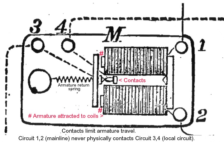
Connection 3 and connection 4 belong to the local station instrument circuit.
(However, if the relay was 'passing the torch' down the mainline - as relays did sometimes - the 3-4 circuit could be the next 50-300 miles of mainline.)
|
Essential Point
Please believe me ! At no point is there any electrical
contact between the mainline circuit
and the local station circuit. The contacts just complete or close the independent station circuit. The station circuit has its own battery to provide power within the station. |
So ... you are thinking ... hmm ... energized magnet ... click ... return spring ... click.
Then what's the big difference between this relay ... and a sounder ?
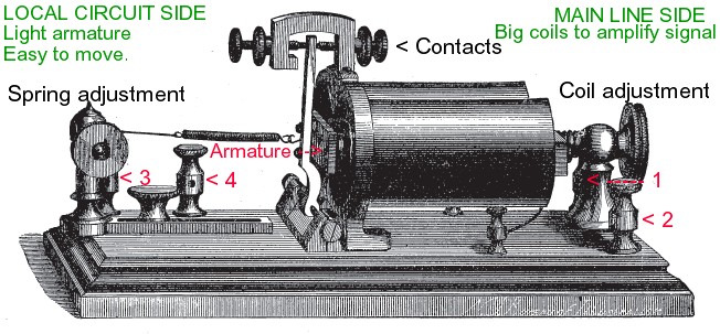
A relay has bigger coils and a smaller armature than a sounder.
The relay must take the faint mainline signal ... and use it to reliably operate the local sounder.
I've put the earlier sounder image below for comparison of coils and armatures ...
Notice all the 'machined screw' adjustments which a skilled operator could make on the relay :
* armature return spring: distance and tension
* contacts: travel and gap
* coil position: 'business end' relative to armature and contacts
We don't care if the relay contacts click so we can hear them ...
we control the local battery attached to the sounder ... so we can make the sounder as loud as we want !
However, if the relay isn't adjusted to crisply energize and de-energize the local station circuit
we will have a lot of trouble understanding the incoming messages.
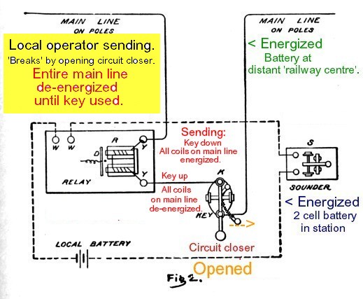
Finally ... to put it all together ...
Here are two sketches of the local instruments.
First: Nothing happening.
Second: Our local Rogers Pass operator wants to send a message.
* * *
First: Nothing happening
Resting = standby = energized state.
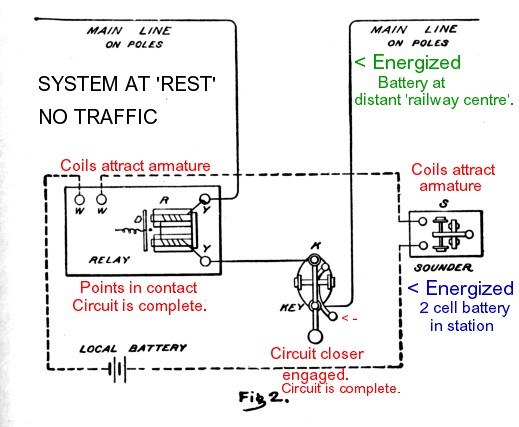
Mainline power is flowing through the relay and key.
The energized relay 'closes' the local circuit ... so current can flow through it from the local battery ... energizing the local circuit.
The local battery powers the sounder ... so the sounder's armature is attracted by its coils.
* * *
Second: Operator 'breaks' to send message from Rogers Pass.
The circuit closer lever on the telegraph key is moved to the right ...
and the circuit is 'opened' - ready for the key to be used.
As a result, the mainline and local circuits are de-energized for a few moments.
The local relay and sounder de-energize and click ... as the springs pull the armatures back from the coils.
At a total of 18 connected telegraph stations on our 'model' mainline circuit from Revelstoke to Field ...
everyone hears their armatures fall away from the magnets and click ...
Then 18 telegraph stations hear their relays and sounders clicking as the Rogers Pass message is sent ...
Key down ... all energized.
Key up ... all de-energized.
* * *
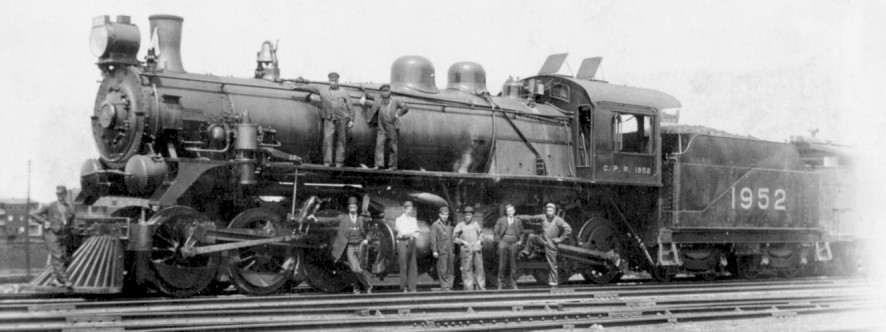
A CPR oddity was a small class of 0-6-6-0 locomotives for use on the Big Hill at Field from circa 1910.
Built at CPR Angus Shops, these 'compounds' were arranged so that the high and low pressure cylinders were only feet apart.
The idea was that this would minimize condensation of the steam between the high and low pressure pistons.
The location of this snapshot and the year are not recorded.
Back to Sitemap