The Switchboard
For now, at least, this is the last of this telegraph series ... one could probably go on for ever ...
duplex transmission ... quadraplex ... submarine cables ... terminal switchboards ... wireless ...
the use of paper tape for high-speed automatic morse transmission (e.g. news and 'Hansard') ... teletype.
My effort has been to interpret the initial technological significance of the telegraph to early Canadian commerce and expansion,
and the typical technology used at intermediate railway stations.
The telephone would end much of the common Canadian use of the telegraph in the early 1900s.
However, while a cadre of experienced railway operators still existed, so did the railway telegraph.
Canadian railways have always loved simple reliable technology that works.
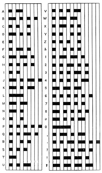
While telegraph code variants evolved to better support local needs, such as characters unique to European languages,
the 'timed' nature of North American 'railway telegraph' characters changed little from the original Vail/Morse invention.
Note below, for example, that 'Y' 'Z' and the 'ampersand' use two 'measures of silence' between some sounds.
The international "Continental" telegraph code is more familiar to most people than this ...
Why wasn't the telegraph code used by the railways changed to reflect some of the advantages of Continental Code in the late 1800s?
Well, it seems that SO many railway operators in the US and Canada were experts at the Vail code ...
that struggling to learn 'new tricks' would seriously impair productivity - and perhaps safety.
In the typical railway way ... the old technology was doing a good reliable job.
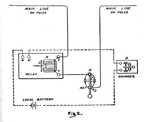
On previous pages, we explored the main line and local circuits.
(diagram below)
Recall that these two circuits do not connect electrically and never swap electrons!
But what happens if there are separate operators and telegraph instruments for the east, west, and/or branch lines?
What if there are two or more main line wires running through the station?
(e.g. divided between railway traffic control use ... and commercial traffic)
What if the 'east line' is broken and the chief operator at division headquarters designates another wire for temporary emergency use?
The Switchboard
Contrasting with the image of a busy army of telephone connection operators with headsets,
inserting plug cords into jacks,
and pulling the plugs when calls were complete ...
The intermediate railway station switchboard might have been altered only a few times per day.
There is an easy way and a hard way to understand this equipment.
Finally, I found the easy way ...
Part A - The vertical switchboard components.
Coming into your intermediate station, you have main line wires : No 1 and No 2.
The railway and telegraph lines radiate north and south from your station.
That is, your trains are either 'northbound' or 'southbound'.
Part of the switchboard is formed by vertical metal plates with 'cutouts' where metal plugs can be inserted.
Often metal discs also form part of the switchboard's face ... as below at 'B C'.
Q1. Where would you insert a metal plug ... so main line wire No 1 would be continuous through your station?
Q2. Where would you insert two metal plugs ... so main line wire No 2 would be continuous?
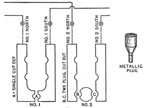
Answer 1 : at A
Answer 2 : at B and C
Hypnotize yourself and believe : 'Vertical plates represent the wires.'
Part B - The horizontal switchboard components.
Forget that you've ever seen the 'metal disc with cutout holes' on the face of the switchboard part above ... don't look back !
At the left of the next diagram, you'll recognize the part of the mainline circuit which is wired through the telegraph key (bottom) and the relay (left).
To make some kind of complete circuit out of this ... you must do something around those metal discs which conveniently have cutout holes.
Connecting them horizontally will not complete the circuit ...
They must be connected vertically somehow.
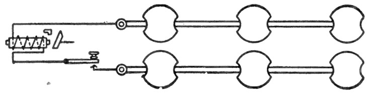
Hypnotize yourself again ... and believe these things without reservation :
'Horizontal contact bars are at the REAR of the switchboard and can be reached by the metal plugs.'
'To connect local instruments to the main line ... power must travel through TWO separate horizontal contact bars.'
Part C - The switchboard components integrated.
to make the main line wire continuous through our intermediate station.
In Part B, we learned that it was necessary to connect BOTH ENDS of a 'telegraph key & relay circuit' ...
by inserting 'a plug above and a plug below'.
Now it's time to put the ideas together.
Below, you can see that the first key is 'cut in' on the No 1 main line wire.
The second telegraph key is 'cut in' on the No 2 main line wire.
(We can pretend the first key is railway traffic control, the second key is commercial and personal telegrams.)
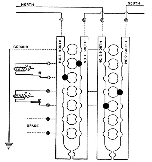
Because the main line circuit always 'grounds' and ENDS at terminals ... sort of by definition ...
we would 'cut' a main line wire if we inserted a plug or two at the local 'ground' on our switchboard.
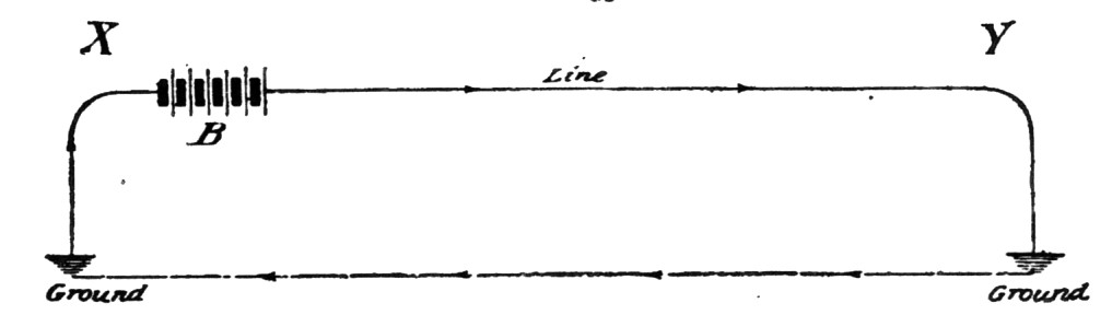
Mainline circuit sketch from before.
In other words, by attaching the 'ground', we would make our station a 'terminal' and block THROUGH signals.
People will then get very mad at us until we disconnected from ground.
However ... if a lineman is working on wire problems ... we may be specifically asked to ground particular wires ...
so sections of the main line circuits can be isolated and tested.
We would get this instruction to ground from the Chief Operator at a terminal ...
after other main line wires were designated as replacements for message traffic.
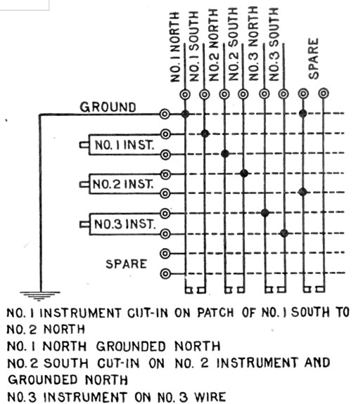
Intermediate Telegraph Switchboard
Graduation Exercise !
The switchboard below represents a rather busy day for those associated with our particular railway telegraph lines.
Evidently, there are all kinds of typical problems ... all happening at once.
However, if it all makes sense to you ... you have what it takes to make changes to the switchboard !
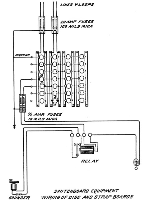
Adding final touches of realistic detail ...
you can see how fuses and grounds were used to protect local instruments and circuits.
Circa 1900, the Telephone is becoming popular within the cities.
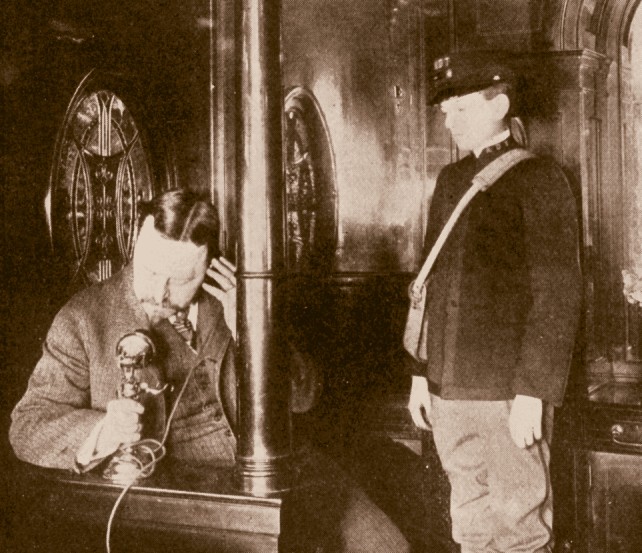
Guess ... where I'm calling from ...
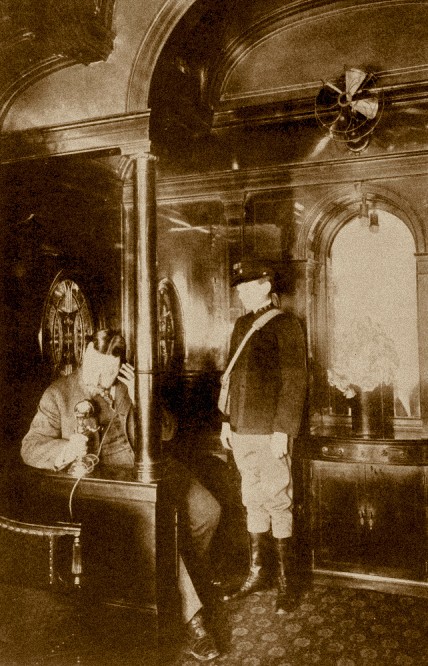
... the ... Train !
"Telephone service on 'The Overland Limited' in the terminal station, Chicago.
Passengers may converse with all city telephone stations up to the time of departure of the train."
* * *
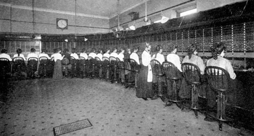
A 'Subscribers' Board - New York City' circa 1900.
... no FaceBook on company time !
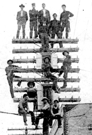
Telephone construction workers during the telephone construction boom.
Newmarket, Ontario 1906
Back to Sitemap